
TAIKE · CUSTOM MANUFACTURING
Precision, made to drawing.
Custom parts, tooling and thermal structures from Suzhou. Share your drawing to discuss material, geometry and quantity.

Precision parts


Components, shaped around your application
Choose a product family to view component images, product details and specifications.
Molds & Components
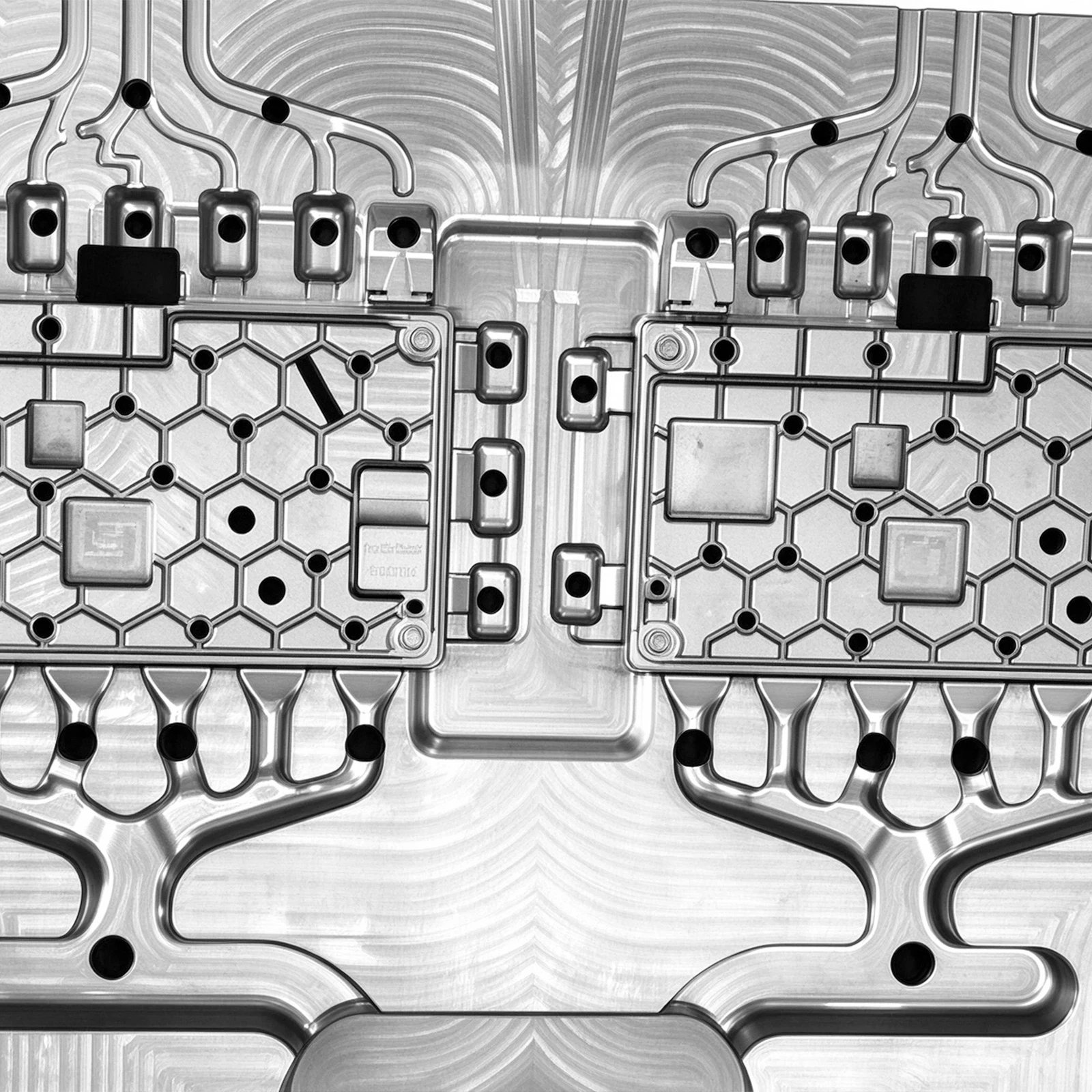
This product family includes die-casting molds, mold ejector pins, ejector rods and inserts.
Fixtures & Components
This product family includes pneumatic fixtures, hydraulic fixtures, pneumatic cylinders and hydraulic cylinders.
Pins & Fasteners
This product family includes locating pins, nuts and screws.
Custom Machined Parts
This product family includes machined aluminum-alloy parts and custom automation components.
Thermal Structures
This product family includes heat-dissipation housings, semiconductor thermal components and liquid-cooling housings.
Housings
This product family includes robot joints and housings.
Processes
Compare machining and fabrication routes
Compare six manufacturing processes and the drawing details needed to assess each.
| Process | Best suited to | The drawing should define |
|---|---|---|
| CNC machining | Plates, housings, brackets and fixtures with pockets, bores and hole patterns. | Material, datum faces, hole and thread callouts, surface requirements. |
| Turning | Round parts such as pins, rivets, sleeves, standoffs, shafts and mandrel components. | Diameters, steps, thread type, concentricity and end-face requirements. |
| Grinding | Locating and sliding surfaces where fit and surface finish come from the drawing. | Fit class, surface finish, heat treatment state before grinding. |
| Wire EDM | Sharp internal profiles, inserts and slide cores in hardened material. | Profile drawing, material and hardness, edge and corner requirements. |
| EDM | Cavities, ribs and deep features that are difficult to cut conventionally. | Feature geometry, depth, surface texture and electrode considerations. |
| Welding | Fabricated frames and assemblies joined from cut or machined elements. | Assembly drawing, joint types, post-weld machining and finish. |
CNC machining
Plates, housings, brackets and fixtures with pockets, bores and hole patterns.
Define: Material, datum faces, hole and thread callouts, surface requirements.
Turning
Round parts such as pins, rivets, sleeves, standoffs, shafts and mandrel components.
Define: Diameters, steps, thread type, concentricity and end-face requirements.
Grinding
Locating and sliding surfaces where fit and surface finish come from the drawing.
Define: Fit class, surface finish, heat treatment state before grinding.
Wire EDM
Sharp internal profiles, inserts and slide cores in hardened material.
Define: Profile drawing, material and hardness, edge and corner requirements.
EDM
Cavities, ribs and deep features that are difficult to cut conventionally.
Define: Feature geometry, depth, surface texture and electrode considerations.
Welding
Fabricated frames and assemblies joined from cut or machined elements.
Define: Assembly drawing, joint types, post-weld machining and finish.
What a tooling or thermal structure project covers
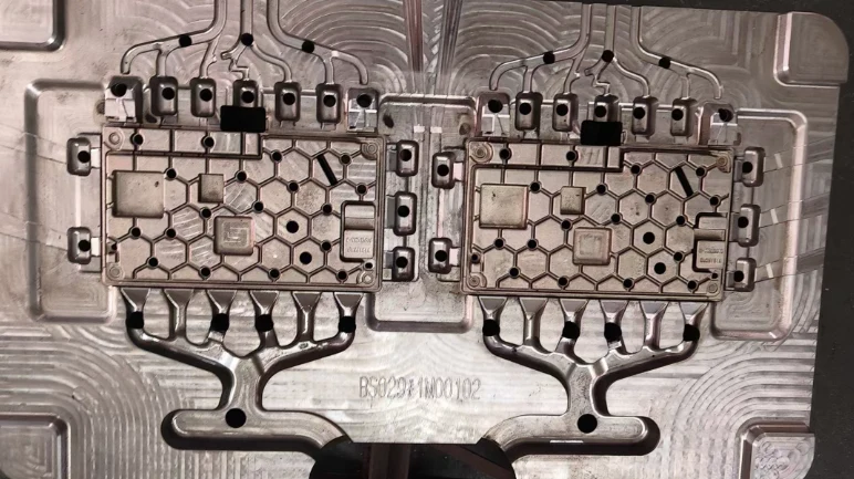
Tooling and thermal parts are usually defined by interfaces rather than by outline. These are the items we review together.
Project scope checklist
- Channel, pocket and rib geometry on the working face
- Contact and mounting faces and their surface condition
- Cutting, grinding or wire EDM routes for hardened or profiled features
- Press tool and fixture interfaces, pins and locating features
- Welded or assembled structures with post-weld machining
Inspection methods and measurement scope
Review the inspection methods and measurement equipment relevant to your drawing.
Drawing review
Features, datums, tolerances and surface notes are read before manufacture so open questions are raised early.
Dimensional inspection
Measured features and the instruments used are agreed against the drawing for each project.
Surface and visual inspection
Edges, faces, threads and finish are checked against the drawing notes and any agreed visual criteria.
Inspection records
If you need measurement records or reports, state this at enquiry so the scope can be confirmed with the order.
Measurement equipment
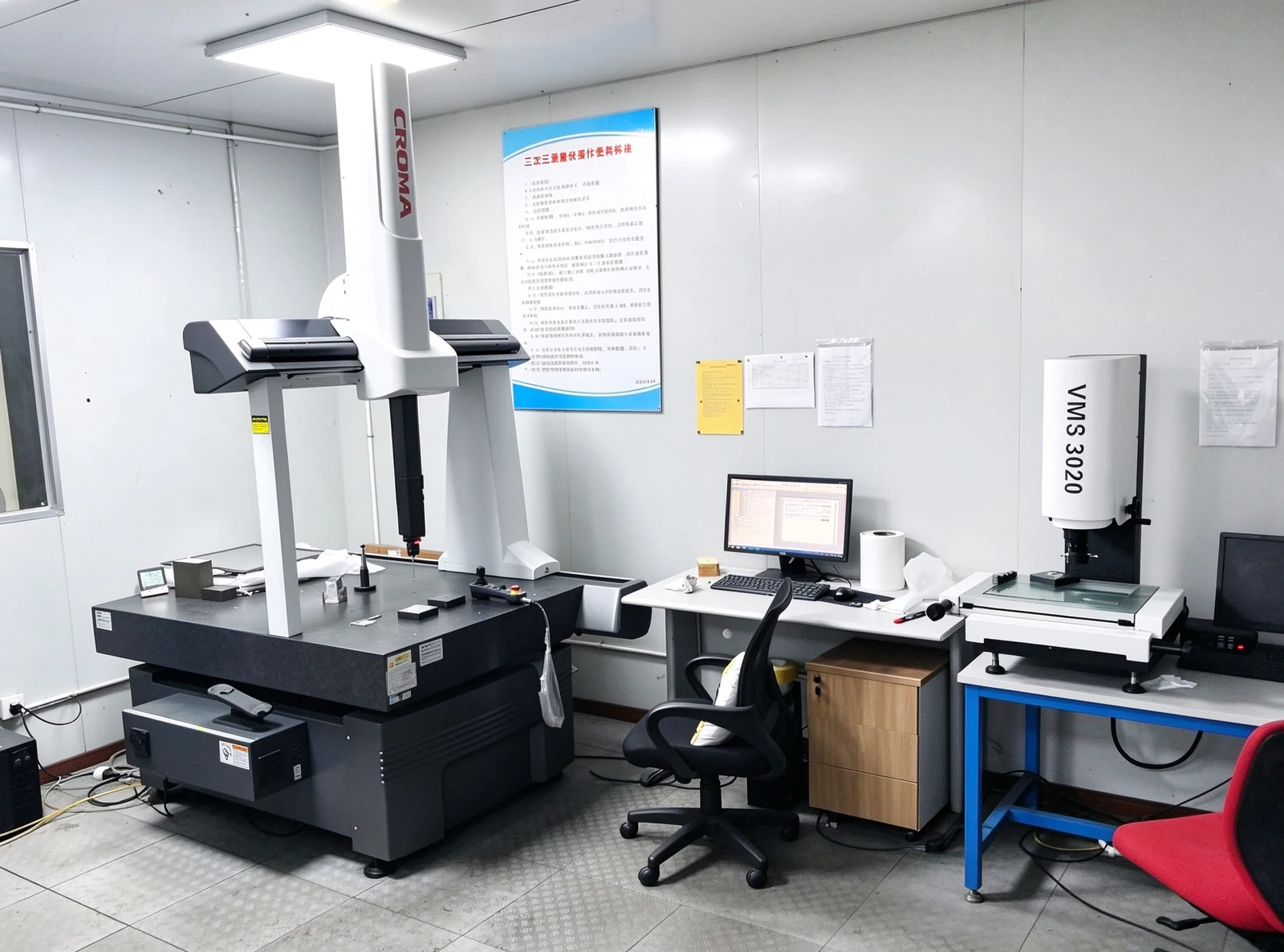
Coordinate measuring machines, 2.5D vision measuring equipment, height gauges and profile projectors support dimensional inspection.
Tooling and component projects
Explore casting tooling, hydraulic fixtures and thermal component work.
Custom tooling
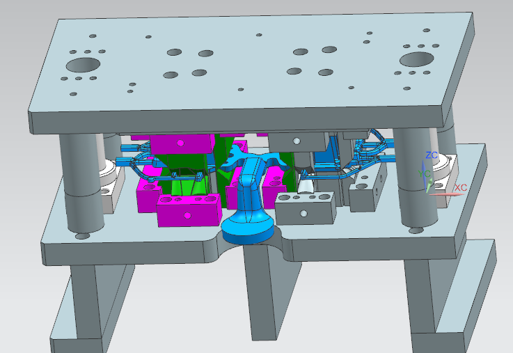
Cutting tooling
Design and manufacture of cutting tooling, drawing on experience with cut-tool projects. Tool configuration is reviewed against the component and process.
Custom tooling
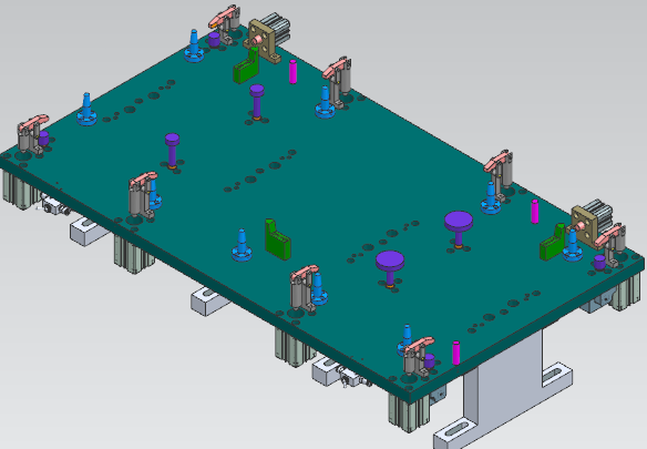
Pneumatic and machining fixtures
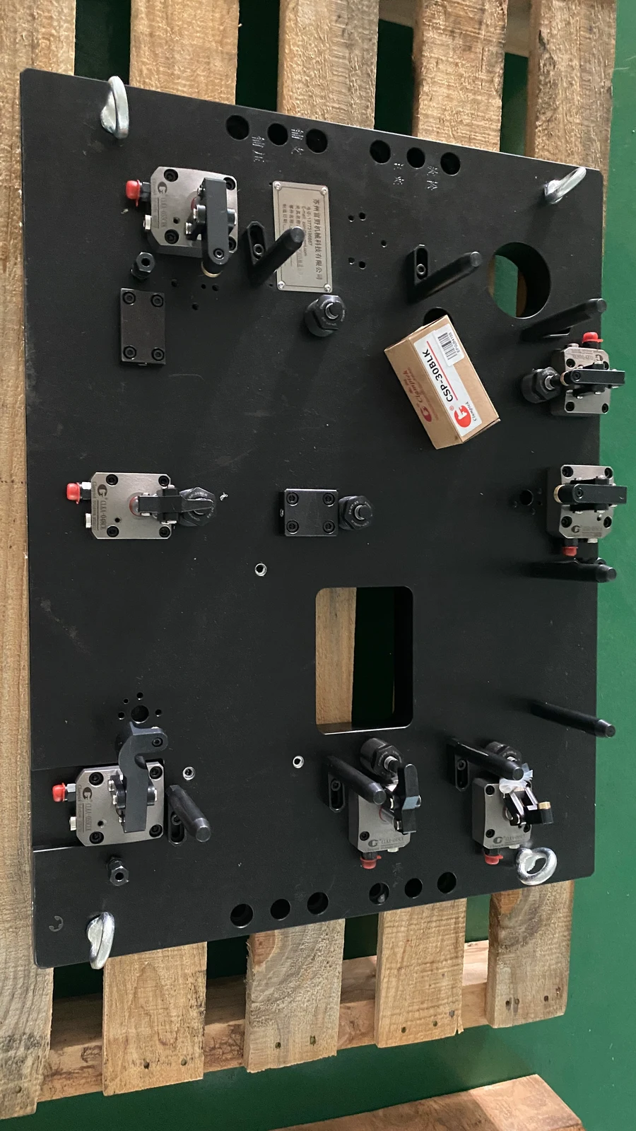
Pneumatic CNC workholding includes horizontal and upright fixture configurations. Clamping, location and machining interfaces are reviewed against the drawing.
Custom tooling
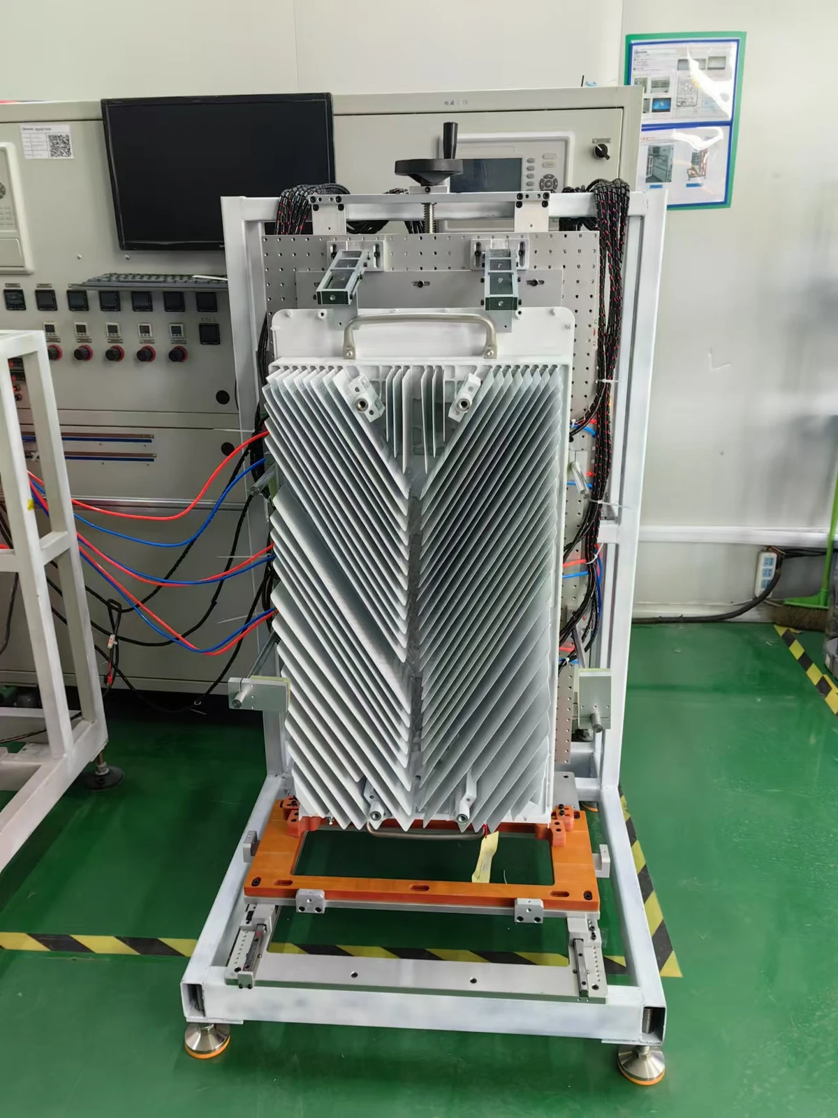
Thermal test fixture
Custom tooling example for thermal test fixture. The tooling configuration is reviewed for the component geometry and process requirements.
Company
Precision manufacturing in Suzhou
Taike brings component machining, tooling and fixture development together for drawing-based manufacturing projects.
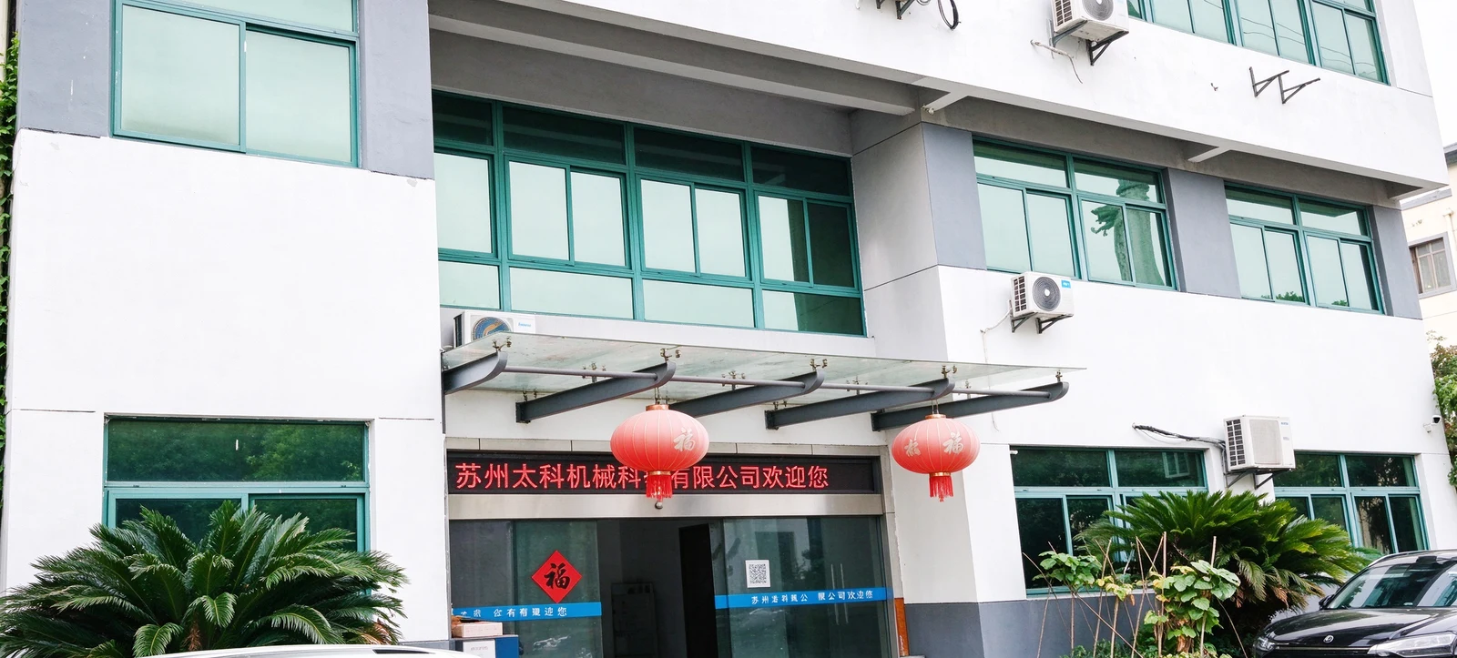
From component machining to tooling and fixture development, Taike works with the drawing, process and assembly requirements of each project.
- Formal company name
- Suzhou Taike Precision Technology Co., Ltd.
- Brand
- TAIKE
- Address
- Building 1, No. 2858 Tian'edang Road, Hengjing, Wuzhong District, Suzhou, China
- Website
- taikeglobal.com
- info@taikeglobal.com
- Telephone
- +86 13773196867
- Business scope
- Suzhou Taike Precision Technology Co., Ltd designs and manufactures custom precision components, tooling and fixtures. Its machining and equipment manufacturing work includes CNC milling, turning, wire EDM, EDM, grinding and welding. The product scope covers mold components, machined parts, aluminum structures, thermal components and housings.
Cooperation references
Manufacturing relationships across telecommunications and precision component industries.
















- Reyi
- Jieshitong
From drawing to manufacturing discussion
Four steps, in order. Nothing is committed until scope is confirmed with you.
Step 1: Send the drawing
Share the drawing, material, quantity and any finish or inspection notes through the contact form or by email.
Step 2: Drawing review
We read geometry, interfaces and tolerances and note anything that needs clarification.
Step 3: Scope confirmation
Process routes, inspection scope and documents are confirmed with you before manufacture is discussed.
Step 4: Manufacturing discussion
Samples, quantity and lead time are discussed according to the drawing, quantity and confirmed order.
Drawing, sample and order questions
Short answers to what buyers usually ask before sending a drawing.